Technical explainer · Published July 30, 2026
A pouch packing line bottleneck is the process condition that limits stable accepted output—not simply the first machine that displays a stop. An HFFS pouch machine may wait because the filler is slow, reject packs because the seal window is unstable, or block because downstream inspection and discharge cannot clear finished pouches.
Quick answer: define the line boundary and accepted-pack metric, record the first cause of every loss, separate starved, blocked, faulted, changeover and quality-hold time, and compare each required process under the same product, pouch, dose and film conditions. The true constraint is the step that cannot sustain the required accepted output after upstream and downstream disturbances are removed. Correct that constraint first; increasing the speed of another station usually adds queueing, waste or stops.
Define accepted output before searching for the bottleneck
Different teams can report different “speeds” from the same run. The HMI may show cycles per minute. A filler may report doses completed. A checkweigher may count inspected packs. Production should base the decision on finished packs that meet the agreed package and product criteria at the selected line boundary.
Record whether the observed time includes planned stops, changeovers, cleaning, film splices, product replenishment and quality holds. A number without its time basis cannot be compared with another run. If the plant uses overall equipment effectiveness, define the same equipment boundary and loss rules before comparing availability, performance and quality.
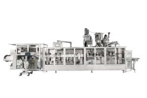
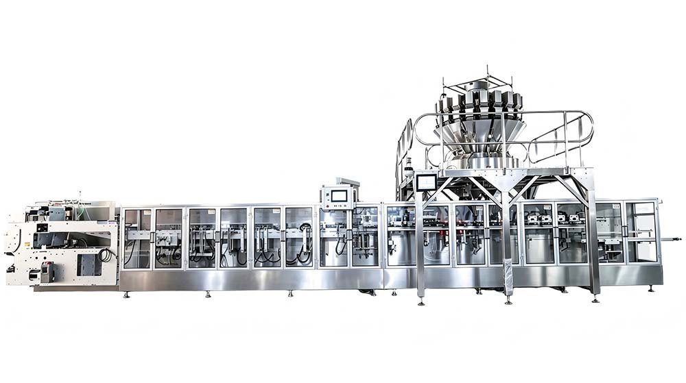
The HMK420 high speed doypack packing machine is specified at 160–200 bags/min in a four-lane configuration. That rating establishes machine capability within its defined pouch and dose range; the project still needs an accepted-output test with the buyer’s agreed product, pouch, film, filler and downstream condition.
The first machine that stops may only be showing the symptom
A stop at the pouch machine does not prove the pouch machine is the constraint. It may be starved by an upstream supply system or blocked by downstream equipment. Likewise, a line can remain mechanically running while accepted output is constrained by rejects, rework, seal contamination or fill-weight variation.
| Observed condition | What it may mean | Evidence to capture | Do not assume |
|---|---|---|---|
| Starved | The required product, pouch web, compressed air or another input is unavailable at the necessary condition. | Supply level, feed status, utility pressure, material-splice status and first upstream stop. | That increasing pouch-machine speed will improve line output. |
| Blocked | Finished pouches cannot leave because inspection, reject handling, accumulation, cartoning or discharge is constrained. | Downstream state, queue level, conveyor status, reject-bin condition and first blocking event. | That the pouch machine caused the stop shown on its HMI. |
| Equipment fault | A component, interlock, process or control condition prevents the intended sequence. | First-out alarm, machine state, station, timestamp, format, product and recovery action. | That the last alarm in the list is the initiating cause. |
| Speed loss | The line runs below its validated target because one process requires more cycle time or repeated micro-stops occur. | Actual cycle trend, station waiting time, micro-stop count and operator intervention. | That a continuous “running” state means full performance. |
| Quality loss | The line produces packs that fail weight, seal, registration, code, appearance or integrity criteria. | Reject reason and lane, sample time, settings, product condition and test result. | That gross pack count equals saleable output. |
| Changeover or cleaning loss | The equipment is available but not yet released for the next acceptable run. | Last good pack, first work step, cleaning end, first trial pack and first approved pack. | That mechanical adjustment time represents total changeover time. |
My Insight
Do not ask “Which machine stopped?” Ask “Which condition first removed the line’s ability to produce an accepted pouch?” That single change prevents downstream blocked stops and upstream starvation from being assigned to the pouch machine. It also exposes quality losses that never create a hard stop but still reduce saleable output.
Record the first cause, not a pile of secondary alarms
A useful loss record must reconstruct the production sequence. If one event triggers several interlocks, later alarms are consequences. Capture the first state change or process deviation, the affected boundary and the reason production could not continue.
OMAC’s PackML framework defines common machine states and PackTags intended to support consistent machine behavior and performance monitoring. It can provide a useful vocabulary, but the buyer and OEM still need to agree how line-level starvation, blocking, quality holds and first-cause ownership will be represented.
Technical basis: OMAC — PackML; ANSI/ISA-TR88.00.02 preview — Machine and Unit States.
Test every required process at the same production condition
A station capacity calculated from an empty-machine cycle is not directly comparable with a filled-pouch run. Product behavior, dose, film, pouch geometry, sealing conditions and inspection logic can change the limiting cycle. Test the complete agreed format and isolate one variable at a time when the line falls short.
| Process area | Typical limiting condition | Evidence to trend | Related guide |
|---|---|---|---|
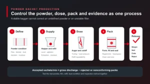
| Product supply | Insufficient refill rate, unstable head pressure, bridging, aeration, temperature or viscosity drift. | Level, supply request, refill duration, pressure, temperature and starved time. | Filling-system selection |
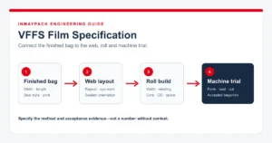
| Film handling | Tension, tracking, registration, splice or roll quality limits stable forming speed. | Web correction, registration error, splice event, unwind status and film-roll identity. | HFFS film specification |
| Pouch opening | Vacuum, air assist, geometry, static, cut quality or timing creates incomplete openings. | Opening verification by lane, vacuum condition, no-open count and pouch samples. | Opening and filling control |
| Filling | Dose time, settling, foam, splash, stringing, cut-off or nozzle motion exceeds the available cycle. | Fill time, nozzle profile, weight trend, product condition and contamination rejects. | Filler decision guide |
| Sealing and cooling | Required dwell, heat transfer, cooling or contamination control cannot support the requested cycle. | Temperature trend, pressure or jaw condition, seal tests, contamination and reject lane. | Seal integrity guide |
| Inspection and reject | Coder, checkweigher, metal detector, vision system or reject confirmation cannot process or clear the flow. | Inspection rate, queue, false rejects, reject-bin condition and confirmation faults. | Project-specific inspection test |
| Discharge and end of line | Conveyor transfer, accumulation, orientation, cartoning or case packing blocks the upstream machine. | Blocked time, queue level, transfer faults, downstream rate and recovery time. | Integrated line acceptance test |
Measure every lane separately on duplex and quadruplex machines
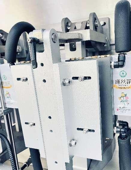
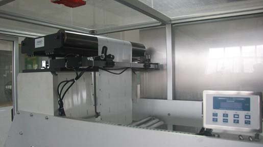
Total output can hide a weak lane. On a multi-lane pouch machine, compare opening success, fill weight, seal results, registration, rejects and intervention frequency by lane. A single unstable lane can limit the whole machine when the control system stops all lanes together or when its rejects consume downstream capacity.
Opening balance
Record verified openings, no-open events, vacuum condition and auxiliary-claw performance by lane.
Filling balance
Trend fill weight or volume, fill time, cut-off behavior and seal-area contamination by nozzle and lane.
Seal balance
Identify samples by lane and compare the approved seal test, appearance and contamination result.
Loss balance
Separate lane-specific rejects and interventions from machine-wide stops, starvation and downstream blocking.
Use the duplex vs single-lane doypack machine guide to decide whether parallel lanes provide useful lifecycle capacity for the product matrix. Lane count only creates value when filling, quality control, cleaning, maintenance access and downstream handling can support it.
Run a controlled trial that can reveal the constraint
A short demonstration with dry film, water or an easy product may confirm motion but cannot prove sustained capacity for a different commercial application. Define the test matrix and hold the production basis constant long enough to observe replenishment, roll handling, temperature stability, micro-stops and downstream accumulation.
- Freeze the test condition: identify product batch and condition, dose, pouch drawing, film roll, code, filler, lane count, machine recipe and downstream scope.
- Define accepted output: state the measurement boundary, duration, planned exclusions and package-quality tests.
- Verify measurement: synchronize clocks and confirm counters, reject reasons, lane identity and first-out events.
- Establish a stable baseline: run at the current validated condition before increasing the target.
- Increase one constraint at a time: change only the variable supported by evidence—supply, filler profile, transport, seal window, inspection or downstream flow.
- Repeat at the agreed duration: a correction is not proven by a few good pouches immediately after adjustment.
- Retain evidence: counters, state history, settings, samples, test results, video and deviation decisions.
Do not bypass safety, inspection or quality controls to create a better speed result. The purpose of the trial is to verify the production system that will be released, not a temporary configuration that cannot be used in normal operation.
NIST describes overall equipment effectiveness as a manufacturing metric combining availability, performance or productivity, and quality. ISO 22400 provides an industry-neutral framework for manufacturing KPIs. Use those concepts only after the equipment boundary, time basis and accepted-product rules are defined for the line being measured.
Measurement references: NIST — manufacturing process and equipment health metrics; ISO 22400-1 — manufacturing operations management KPIs.
Correct the constrained process, then verify the complete line again
The right correction depends on the first limiting condition. A larger upstream buffer can reduce starvation but cannot fix unstable dosing. More filler heads can reduce fill time but cannot solve a seal window that fails at the higher cycle. Faster discharge can remove blocking but cannot improve product supply.
| Confirmed constraint | Possible correction path | Required re-verification |
|---|---|---|
| Product supply | Feeder, pump, tank, hopper, agitation, temperature control, refill logic or buffer capacity. | Stable supply condition, fill accuracy, product integrity and full-duration run. |
| Filling cycle | Filler technology, multiple doses, nozzle profile, cut-off, product conditioning or lane distribution. | Weight or volume, contamination, fill time and seal results by lane. |
| Film or forming | Material specification, roll quality, tension, guiding, registration, forming or splice method. | Pouch geometry, registration, opening, seals and waste across representative rolls. |
| Sealing process | Film sealant, jaw condition, heat transfer, pressure, dwell, contamination control or cooling. | Approved seal tests at startup, steady state, after stops and at target cycle. |
| Inspection or discharge | Inspection rate, reject logic, conveyor transfer, accumulation or downstream machine capacity. | Reject confirmation, queue recovery, blocked time and accepted end-of-line output. |
| Changeover or cleaning | Format parts, recipes, access, cleaning design, task sequence, verification or staffing. | Last-good to first-approved time and repeatable production release. |
| Recurring equipment loss | Root-cause correction, preventive task, component redesign, utility correction or spare strategy. | Failure recurrence, maintenance evidence and sustained production run. |
Write the final capacity basis into the URS and factory acceptance test: product, dose, pouch, film, lane count, utilities, upstream and downstream scope, run duration, accepted output, reject rules, quality tests, planned exclusions and evidence to retain. The stand-up pouch machine FAT checklist provides the acceptance framework, while the pouch packing machine changeover guide separates sustained production capacity from format-change and startup losses.
If the first loss occurs at a machine-to-machine handoff, use the packaging line integration checklist to assign signal ownership, blocked and starved behavior, buffer logic, reject handling and the FAT evidence required to close that boundary.
Connect capacity analysis to reliability and recovery
Once the immediate constraint is corrected, continue monitoring the loss structure. A different station may become limiting, and repeated micro-stops can accumulate into a larger capacity loss than one visible breakdown. Keep production, quality and maintenance records connected to the same machine, format, lane and failure mode.
Technical references
- International Organization for Standardization, ISO 22400-1:2014 — Key performance indicators for manufacturing operations management.
- National Institute of Standards and Technology, manufacturing process and equipment health metrics paper.
- Organization for Machine Automation and Control, PackML overview and implementation resources.
- International Society of Automation, ANSI/ISA-TR88.00.02 preview — Machine and Unit States.
Need a line-capacity review before you approve the machine layout?
Send the product, dose range, pouch drawing, film structure, target accepted output, lane preference, upstream supply and downstream equipment. INMAYPACK can review the likely constraints and define a project-specific trial basis.
Reply: sales@ewpackmachinery.com · WhatsApp: +86 18658799162