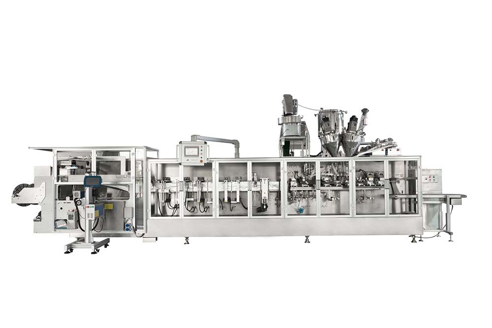
Components of a Horizontal Form Fill Seal Machine: A Station-by-Station Map
Updated: September 21, 2026
About INMAYPACK Engineering Team
INMAYPACK is a packaging machinery brand based in Shanghai, China, founded in 2009. The INMAYPACK Engineering Team publishes practical guidance on doypack, sachet, premade-pouch and coffee packaging. Machine suitability, performance and service terms depend on the confirmed model, configuration, product, package and agreed project scope.
HFFS pouch machine components · Published July 27, 2026
A component list is useful only when it follows the material path. A roll-stock pouch line does not “form, fill and seal” in three isolated actions. It hands a flexible web through a chain of controlled references: edge position, pitch, fold geometry, seal location, pouch grip, mouth opening, fill position and final top-seal condition.
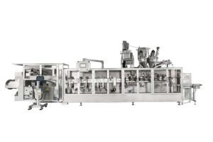
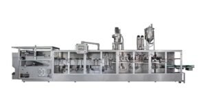
Quick answer: the core components of a horizontal form fill seal pouch machine are the film unwind and tension system, web guide or registration control, pouch former, optional zipper or fitment section, bottom and side sealers, film pull and cutting mechanism, pouch transfer grippers, opening system, filling interface, top-seal and cooling stations, discharge, and the PLC/servo/pneumatic control architecture that synchronizes them.
The name HFFS is also used for horizontal flow wrappers that form a tube around a product. This guide is narrower: it covers the horizontal pouch architecture that folds roll stock into panels, forms open-top pouches, separates or transfers them, fills them and closes the top. That boundary matters when comparing quotations, because two suppliers can both write “HFFS” while offering very different material paths.
1Unwind & tension
2Guide & register
3Fold & form
4Bottom / side seal
5Pull & cut
6Grip & transfer
7Open & fill
8Top seal & cool
9Inspect & discharge
An HFFS pouch line is a sequence of handoffs. A stable station cannot compensate indefinitely for an unstable reference arriving from upstream.
Film-to-pouch section
The first four stations create the reference that every downstream station inherits
A printed web can look correct at the reel and still arrive at the sealer with lateral drift, unstable pitch or a distorted fold. Diagnose the material path in order; do not start by changing a downstream jaw because the finished pouch is crooked.
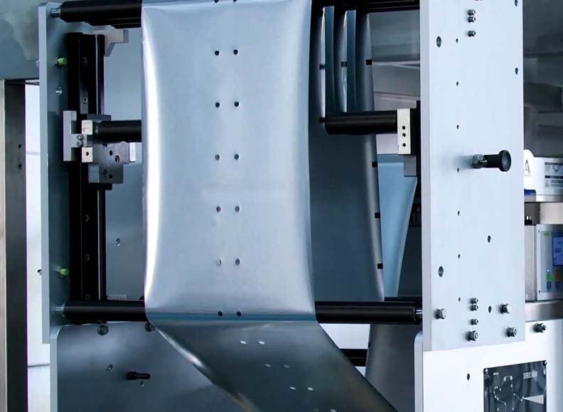
01 · Unwind and tension
Deliver film without stretching or starving the next station
Controls: reel support, brake or driven unwind, dancer/buffer response, roller alignment and web tension.
Watch for: telescoped rolls, abrupt tension changes, wrinkles and a dancer that reaches its travel limit. An edge guide can move the web sideways; it cannot cure unstable longitudinal tension.
To quantify the material lost during threading, restart, registration correction and format changes, use the HFFS film waste reduction guide and keep each loss event in a separate reason-code bucket.
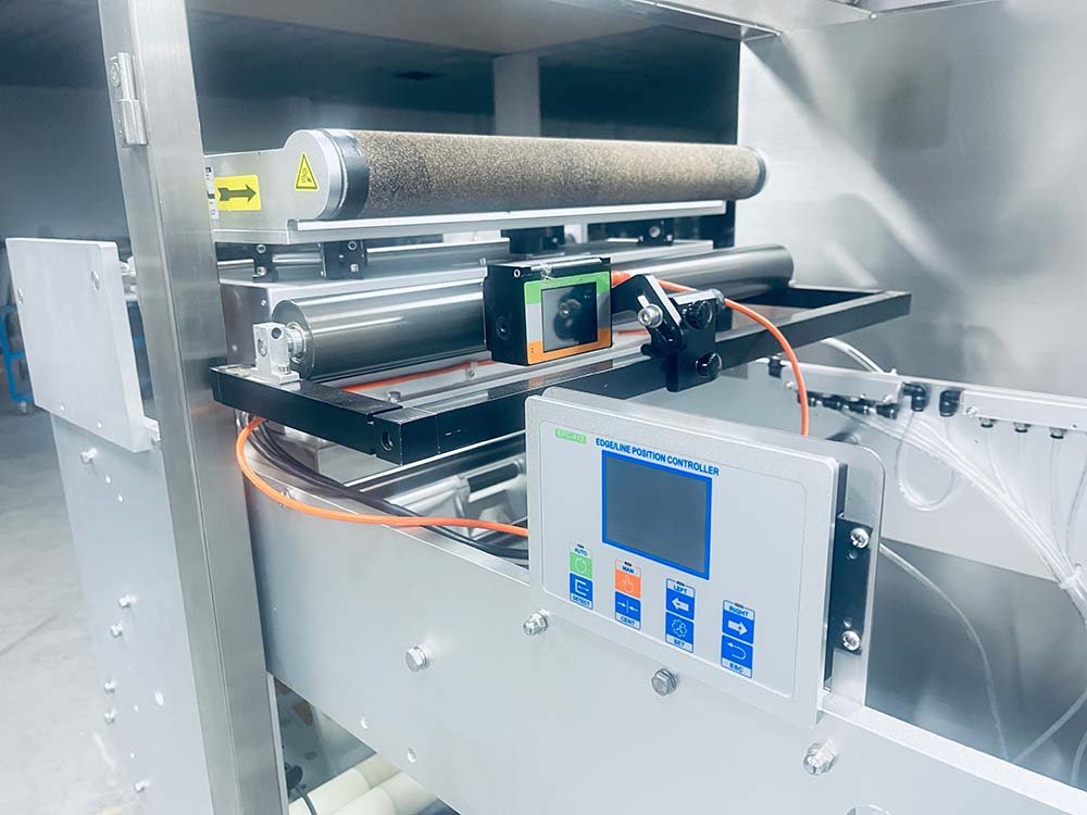
02 · Web guide and registration
Separate lateral position from print pitch
Controls: an edge or line sensor corrects cross-machine position, while a registration-mark sensor gives the controller a repeatable print reference.
Watch for: transparent or reflective film, weak mark contrast, sensor contamination, incorrect sensitivity and a correction actuator that repeatedly hunts.
03 · Former, fold and gusset
Turn a flat web into the intended pouch cross-section
The forming plow creates the two panels; guides and creasing elements establish the fold, bottom gusset or other profile. Optional zipper application must also enter this geometry at a controlled position.
The acceptance reference is the physical pouch drawing, not only the nominal film width. Use the separate guides for bottom-gusset geometry and roll-stock zipper application when those features are in scope.
04 · Bottom and side sealing
Create a repeatable seal before the pouch is separated
Seal bars must bring the intended laminate layers together with a controlled combination of jaw condition, heat, pressure, contact time and cooling. Different seal zones can need different settings.
A displayed temperature is only one input. Confirm the finished seal with the agreed package test method and actual production film; the seal-integrity guide explains that process window in detail.
The film path establishes alignment and fold geometry before pouch sealing. Roller condition, threading and tension should be checked before correcting downstream symptoms.An edge-position sensor controls lateral web location. Registration pitch and longitudinal tension remain separate control tasks.
Pouch-to-finished-pack section
After forming, the machine must preserve position while the pouch changes shape and mass
05 · Film pull and cutting
Convert the controller’s pitch into a physical pouch
Pull rolls or servo-driven transport advance the web by the commanded index. The cutter must separate the pouch at the intended location inside the seal area without dragging the web or leaving connected edges.
If the cut walks relative to the artwork, check whether the error begins as registration drift, accumulated pull error, film slip or cutter timing before moving the knife.
06 · Pouch transfer and grippers
Hold the same reference through every intermittent move
Grippers support the pouch through opening, filling, top sealing and discharge. Their spacing, clamping point, parallelism and motion profile affect mouth position and top-seal presentation.
A pouch that enters the gripper at the wrong height can create several apparently unrelated faults downstream. Check the first bad handoff, not only the last visible defect.
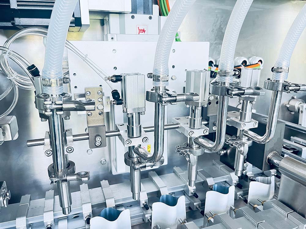
07 · Opening and filling
Make the bag mouth and filler share one coordinate system
Vacuum cups, mechanical opening support and optional air assist create clearance for the nozzle or funnel. The filling device—pump, auger, weigher or other doser—must then discharge within the available cross-section and cycle time.
The pouch opening and filling guide separates opening force, gripper position, nozzle clearance and product trajectory so they can be tested independently.
08–09 · Top seal, cooling and discharge
Close a clean mouth and release a stable package
The top-seal zone needs the correct film presentation and an uncontaminated seal band. Product settling, de-aeration, gas flushing, dust extraction or a pouch-mouth cleaner may be required before sealing for some applications.
Cooling and discharge must not bend or load a seal before it has stabilized. Any checkweigher, leak test, vision inspection or reject device should be defined as a separate interface, not assumed from the word “automatic.”
The filling interface is more than the dosing head: pouch support, opening geometry, nozzle travel, discharge timing and product behavior must all fit the same process window.
Controls are the coordination layer, not a tenth independent process
The PLC and HMI hold recipes, interlocks and alarm logic. Servo axes, pneumatic valves, sensors and temperature controllers execute the sequence. A useful control description therefore states which station owns each axis, which sensor confirms each transition, what happens after a missed confirmation and which settings are protected by access level.
Architecture check: “servo controlled” is incomplete unless the quotation names the controlled axis and its purpose. Film pull, gripper transfer, filler motion, sealing-jaw motion and unwind control are different tasks; one servo label does not describe all of them.
Specification and acceptance
Turn the station map into evidence for the quotation and FAT
The same machine frame can be configured differently for powder, granules, free-flowing liquid, viscous product, standard doypack, zipper pouch or shaped pouch. Ask the supplier to connect each proposed component to your film, pouch drawing, product behavior and acceptance method.
Subsystem
Define before order
Evidence to request
Film handling
Roll dimensions, unwind direction, core, splice rule, web guiding and registration method
Approved film specification, threading diagram and marked sample roll
Pouch forming
Finished drawing, gusset, zipper/fitment, notch, hole and seal-band geometry
Dimensioned pouch drawing and formed empty samples
Filling interface
Product state, dose range, density or viscosity behavior, temperature, particulates, foaming and cleaning boundary
Representative product, agreed test condition and filler interface drawing
Top seal
Required clean zone, de-aeration/gas/dust controls, seal verification and cooling
Filled samples and the agreed package test method
Controls and safety
Recipes, alarm response, interlocks, guarded access, utilities and upstream/downstream signals
I/O list, utility schedule, layout and approved FAT protocol
Send the actual printed roll and representative product, not only nominal dimensions.
Record the first station where a defect becomes measurable.
Verify change parts, tools and recipe changes for every approved format.
Define acceptance limits in the URS or approved FAT protocol; do not invent them during the test.
Map your pouch and product to the right HFFS stations
Send the pouch drawing, roll-film specification, product details, target output and required options. INMAYPACK can review the interfaces and propose a testable machine configuration around the roll-stock stand-up pouch platform.