Documented engineering build
This record examines a factory-built filling, rinsing and capping system documented for premade center- and corner-spout pouches. It separates the configuration visible in the source material from performance that still requires a controlled acceptance test.
The available source configuration records a 12-head indexed platform for liquid or paste products, a 30–300 mL filling reference, a 240 L hopper, piston-pump dosing, automatic pouch feeding, filling, cap presentation, capping and discharge. A 13,000–15,000 pouches/hour figure is documented at 100 mL, but it is not presented here as a verified customer production result.
Recorded project basis
What the source configuration says
These values belong to this documented reference. They should not be copied into another quotation until the product, pouch, spout, cap, utilities and acceptance basis are confirmed.
| Item | Documented reference | Project boundary |
|---|---|---|
| Product family | Liquid and paste | Real viscosity, temperature, particles, foaming and cut-off behavior still control the filling system. |
| Filling range | 30–300 mL | Usable range must be checked with the selected piston set and approved product. |
| Metering | Piston-pump reference; servo filling | Product-contact parts are documented as 304 stainless steel; hygiene and cleaning requirements remain project-specific. |
| Hopper | 240 L; 304 stainless steel reference | Refill method, level control, agitation, temperature control and upstream interface must be defined. |
| Center-spout pouch | W60–160 × H60–280 mm | Final compatibility depends on the controlled pouch, spout and cap drawing plus samples. |
| Corner-spout pouch | W60–340 × H60–300 mm | Dedicated carriers or change parts may be required for each approved format. |
| Electrical reference | 380 V, 50 Hz, 15 kW | The destination supply and installed-load boundary must be confirmed before order. |
| Machine reference | Approx. 4500 × 3000 × 2400 mm; approx. 2400 kg | Allow for access, cap loading, pouch loading, drains, product supply and maintenance clearance. |
| Indexing and controls | Cam indexer, PLC, touchscreen, recipe storage reference | Language, access level, alarm list, data, signals and recipe approval belong in the URS. |
For model selection across the wider series, use the 6-, 8- and 12-head spout pouch filling and capping machine comparison. This record focuses only on the documented 12-head build.
Physical process
The recorded sequence connects pouch presentation to finished discharge
Head count alone does not define the line. Every feeding, dosing and closure step must support the same accepted output.
Load premade spout pouches
The source sequence begins with manual loading onto the specified rod or feed arrangement. Pouch orientation, refill interval and operator access are part of the cycle.
Feed and index carriers
The machine transfers approved pouches into the indexed handling path. Presence checks and the response to an empty position should be defined for the project.
Meter the product
The documented piston system doses through the fitted spout. The product condition, fill volume, replenishment and cut-off behavior must be tested together.
Rinse where included
The recorded build includes a rinsing-related configuration. Media, pressure, contact point, splash control, drainage and acceptance method require written scope.
Present and apply caps
Caps are elevated, oriented and transferred to the capping stations. Cap geometry, seating, torque and leakage checks must use buyer-supplied samples.
Discharge and record
Finished pouches leave the indexed section for the agreed collection, inspection or downstream route. Output should be based on conforming packs, not empty machine cycles.
Visible engineering interfaces
Pouch loading and cap supply are part of the machine task
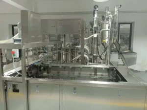
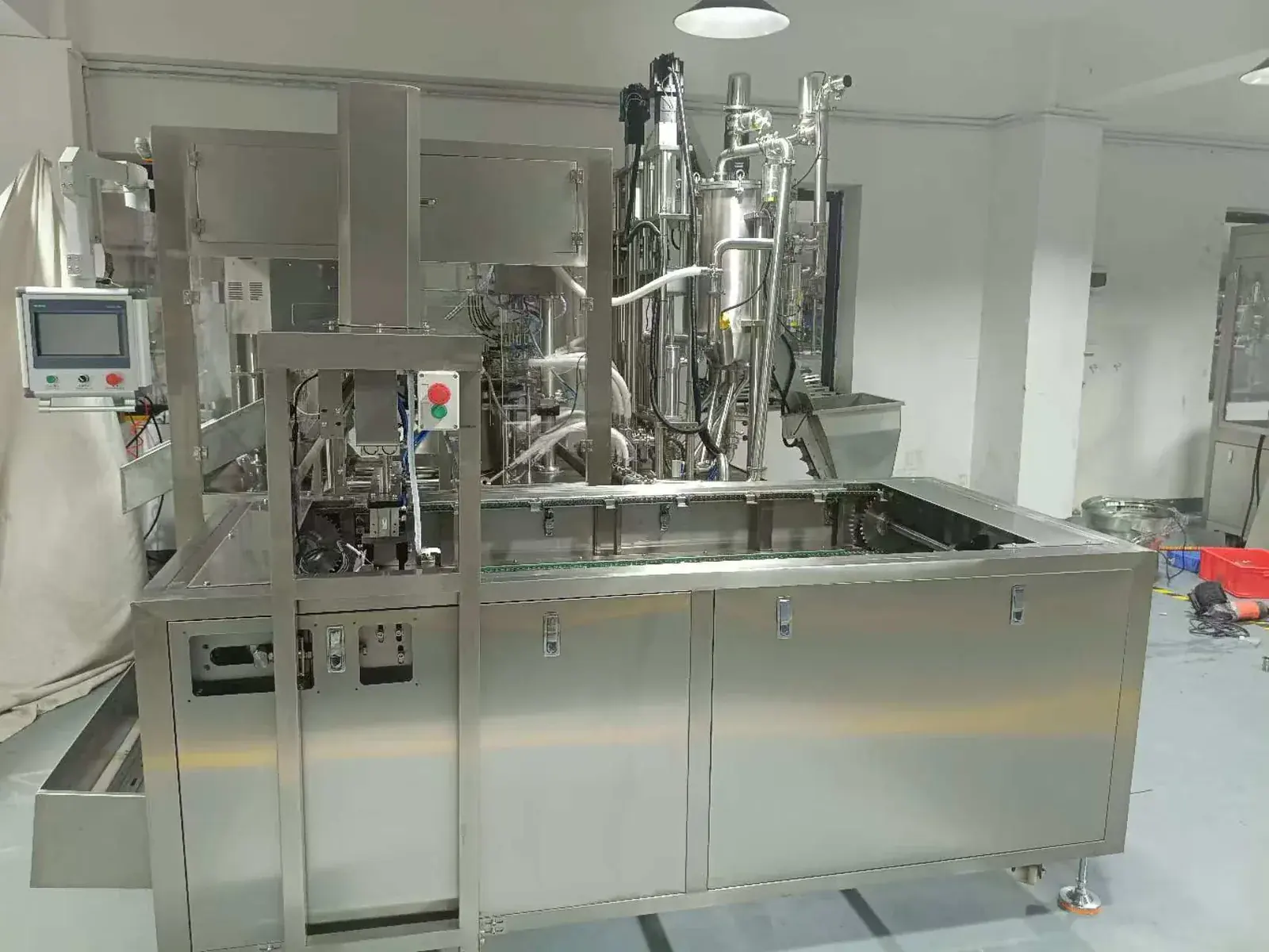
The factory photographs show more than a stainless-steel frame. They expose the interfaces that can starve or block the indexed platform if they are left outside the acceptance plan.

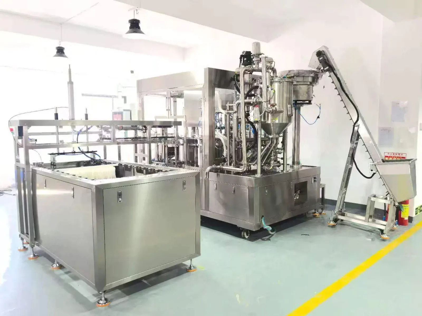
Define the hopper boundary
State how product reaches the 240 L reference hopper, the refill rate, level control, cleaning connection, drainage and responsibility for upstream preparation.
Test real pouch variation
Use controlled center- or corner-spout pouches and include normal stiffness, thickness, spout position and dimensional variation—not only ideal samples.
Control cap identity and recovery
Record cap drawing, orientation, feed rate, low-level response, cross-thread checks, seating criteria and the approved torque or leak method.
Reserve working clearance
The machine envelope is not the total installed footprint. Include operator loading, product piping, cap replenishment, service access, drains and downstream transfer.
Performance boundary
How to interpret the documented output reference
The source document records 13,000–15,000 pouches/hour at 100 mL. This is not an unconditional production promise. The usable result changes with product flow, pouch and cap feeding, fill accuracy, rinsing, closure quality, refill interruptions, rejects and downstream handling. A comparable quotation must state the product and pack condition, test duration, staffing and definition of a conforming finished pouch.
Station-level review
Filling, rinsing and capping must be accepted as one sequence
A stable dose can still become a rejected pack if product reaches the closure area, the cap is mis-presented or a downstream stop blocks discharge.
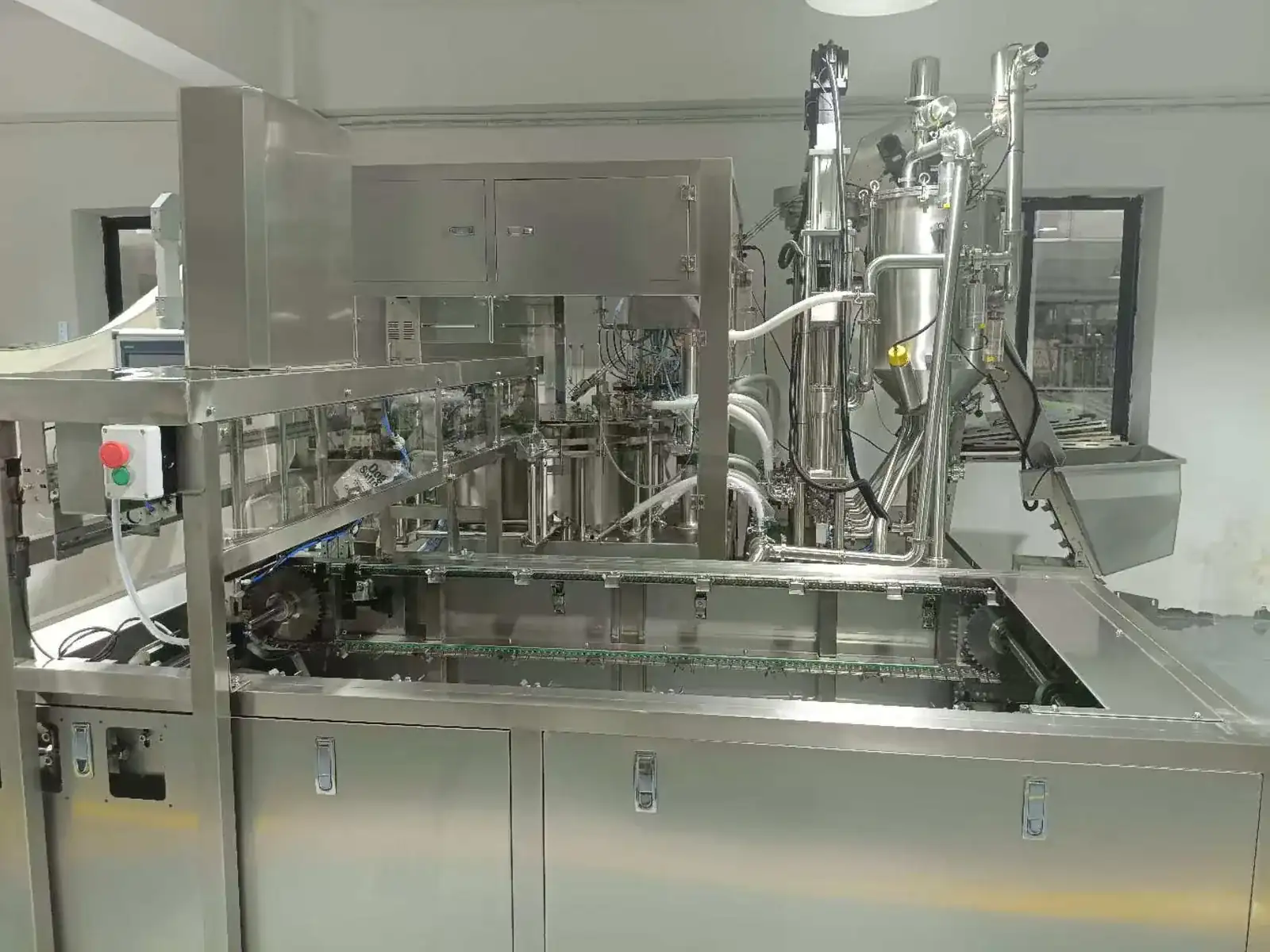
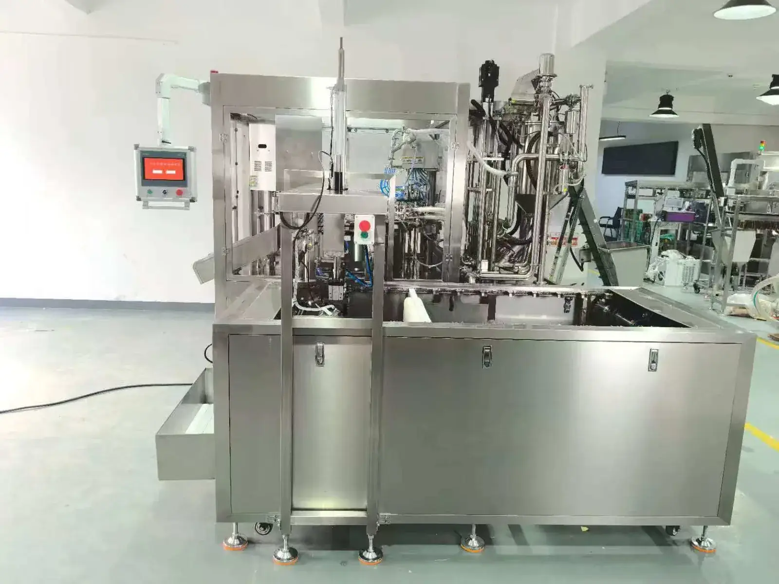
Dosing window
Check fill accuracy and cut-off at the minimum, normal and maximum approved doses with the actual product condition.
Cleaning boundary
Define which product paths are cleaned in place, which parts are removed, and how cleaning is verified before the specification is frozen.
Closure quality
Agree cap seating, torque or leak checks, sampling, reject logic and the response to low or interrupted cap supply.
Evidence discipline
What the available evidence proves—and what it cannot prove
| Available evidence | Reasonable conclusion | Do not infer |
|---|---|---|
| Original factory photographs | A physical multi-station stainless-steel machine, pouch loading area, product system and cap-feed arrangement were built and photographed. | That the machine passed a named customer's FAT, was shipped or achieved field production. |
| Project configuration document | The listed ranges, utilities, dimensions, materials and process sequence were recorded for this reference configuration. | That every value applies to every liquid, paste, pouch, spout or cap. |
| 100 mL speed reference | 13,000–15,000 pouches/hour is a source-document planning reference for the documented platform. | Guaranteed good output without a controlled product, package and acceptance test. |
| Component schedule | The source document identifies PLC, touchscreen, servo, power, pneumatic, sensing and relay references. | That substitutions can never occur or that one brand alone proves line performance. |
Customer identity, country, product brand and commercial information are intentionally omitted. No generative marketing graphic is used as evidence for a customer outcome.
For a comparable project
Build the FAT before treating the reference as a production result
A new project should convert the planning reference into an agreed, recorded acceptance result using the buyer's actual product and packaging components.
- Identify the controlled product, temperature, viscosity, particles, foaming and refill method.
- Record each pouch, spout and cap drawing, sample revision, dimensional window and required change parts.
- Define fill-volume checks, closure seating, torque or leak criteria, sampling and reject rules.
- Set the run duration, staffing, planned stops, low-product and low-cap challenges, restart and changeover checks.
- Count conforming finished pouches separately from total cycles, rejects and open machine positions.
- Record settings, alarms, counts, samples, deviations and signed open items before shipment release.
Use the stand-up pouch machine FAT checklist to build the acceptance record, and review service and project support boundaries before commercial comparison.
Continue the decision path
Use the evidence that matches your packaging route
Engineering questions
12-head spout pouch project FAQ
What package does this machine reference handle?
It is documented for premade pouches with a fitted center or corner spout. It does not form the pouch from roll film or weld a new spout into an unspouted pouch.
What products and fill volumes are documented?
The source configuration lists liquid and paste products with a 30–300 mL reference range. Actual suitability depends on viscosity, temperature, particles, foaming, shear, cut-off and cleaning requirements.
Does the machine guarantee 13,000–15,000 pouches/hour?
No unconditional guarantee is made here. That figure is documented at 100 mL for the source configuration. Accepted good output must be proved with the specified product, pouch, cap, staffing, refill conditions, test duration and reject rules.
Can the same build run center- and corner-spout pouches?
The source document records dimensional windows for both formats, but every pouch, spout and cap combination must be checked. Carriers, guides, recipes or dedicated change parts may differ.
What should a buyer send for a similar project review?
Send the product specification and samples, dose range, pouch/spout/cap drawings and samples, target conforming output, cleaning method, utilities, floor plan, downstream interface, destination requirements and FAT acceptance rules.
Is this a customer performance case study?
This is an anonymized engineering build record based on original factory photographs and a project configuration document. It intentionally makes no claim about customer identity, shipment, commissioning, passed acceptance or field production.
Review a real project basis
Send the product, pouch, spout and cap—not only a target speed
INMAYPACK will review the filling range, product behavior, pouch and closure samples, loading method, cleaning scope, accepted output and FAT basis before recommending a 6-, 8- or 12-head configuration.