Packaging systems configured around your application Defined project scope

Share your requirements • sales@ewpackmachinery.com

Premade spout pouches · 6, 8 & 12 head

Spout Pouch Filling and Capping Machine – 6, 8 & 12 Head

Fill through the spout. Apply the cap. Define the finished pouch.

Configure an automatic filler and capper for premade pouches that already have a fitted spout. INMAYPACK matches the head count, metering system, pouch carrier, cap handling, cleaning scope and acceptance test to the real product and pack.

Liquids & pastes30–1500 mL documented series rangeCenter & corner spoutsProject-specific FAT
Compare 6, 8 & 12 Head

The combined range belongs to the series, not every configuration. Accepted output and format fit must be confirmed with the selected machine, product, pouch, spout and cap.

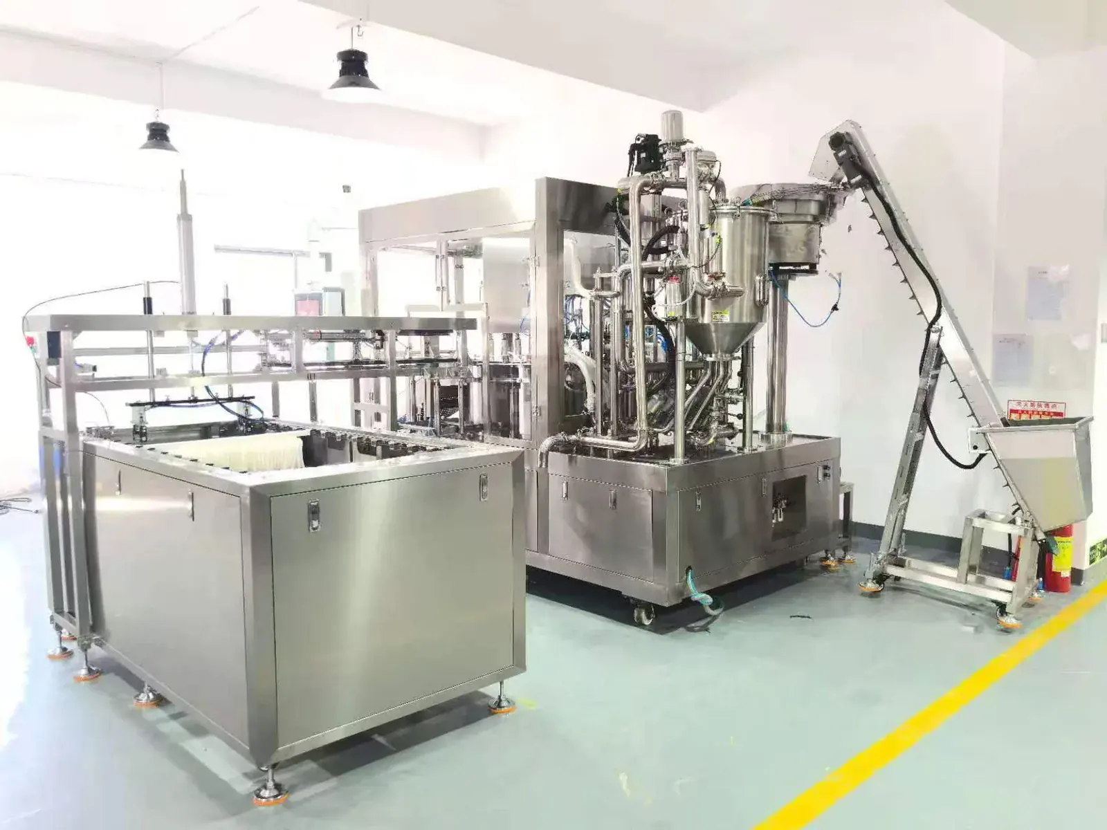
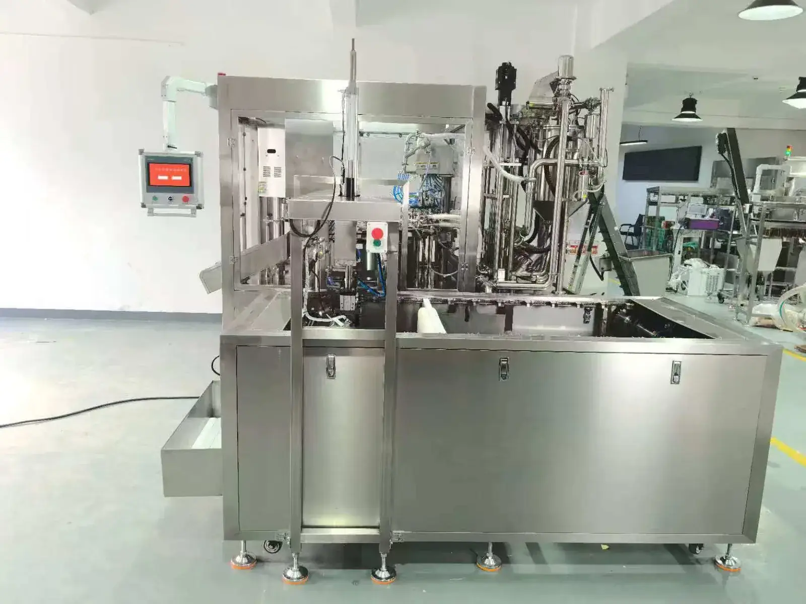
12-head premade spout pouch filling and capping machine
12-head premade spout pouch platformDocumented equipment reference. The selected filler, cleaning scope, cap handling and supplied modules are defined in the proposal.

Choose the correct packaging route

This page is for pouches with the spout already attached

The machine receives premade spout pouches, indexes them through filling, adds a rinsing step where specified, feeds and tightens caps, then discharges the finished packs. That boundary prevents this page from competing with machines that form the pouch or weld the spout.

Use this 6/8/12-head series when

The supplied pouch is already spouted

  • Product enters through the existing spout
  • The closure is applied after filling
  • Pouch, spout and cap samples can be supplied for trials
  • Output will be approved from good finished pouches

Use another INMAYPACK route when

The package is made or modified on the line

  • HMS160 roll-film HFFS route forms the pouch and welds the spout
  • SG260 premade-pouch route opens, fills, top-seals and inserts the side spout
  • Non-spouted pouches need a sealing process instead of capping
  • A validated aseptic process must be separately engineered and documented

Configuration comparison

Compare documented 6-, 8- and 12-head references

Head count is only one selection variable. Fill volume, product behavior, pouch dimensions, cap presentation, cleaning and required accepted output determine which platform should be quoted.

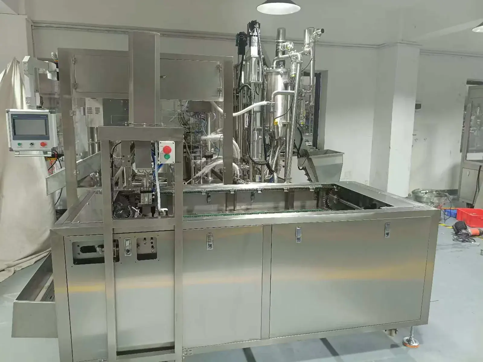
6-head spout pouch filling and capping machine with piston filling and CIP piping
6-head reference

Moderate output with piston filling

Documented for 30–500 mL liquid and paste projects, with a compact output reference and wide center- or corner-spout format windows.

Fill range30–500 mL
MeteringPiston pump
Reference speed≈130/min at 100–200 mL
300 mL reference≈100/min
View documented 6-head details

80 L 304 stainless-steel hopper; 380 V 50 Hz; 8 kW; approx. 1000 kg; approx. 3100 × 3000 × 2500 mm. Center-spout reference: W60–240 × H60–300 mm. Corner-spout reference: W60–360 × H60–320 mm.

The source configuration includes piston filling, rinsing and CIP-related piping. Confirm the final cleaning boundary in the quotation.

8-head spout pouch filling and capping machine with pouch feed track
8-head reference

Wider documented filling range

Documented with a 60 L gear-pump filling reference for projects that need a broader 30–1500 mL planning range.

Fill range30–1500 mL
MeteringGear-pump reference
150 mL reference8,000/hour
500 mL reference6,000/hour
View documented 8-head details

180 L hopper; bag width 50–330 mm and length 50–300 mm; 380 V 50 Hz; 8 kW; approx. 1000 kg; 304 stainless-steel frame and product-contact parts; cam indexer.

Pump capacity and usable fill range must be checked against viscosity, temperature, particles, refill method and the required cycle.

12-head spout pouch filling and capping machine for high-output premade pouches
12-head reference

Higher-output small-dose platform

Documented for 30–300 mL with a 100 mL output reference of 13,000–15,000 pouches/hour.

Fill range30–300 mL
MeteringPiston pump
100 mL reference13,000–15,000/hour
Hopper240 L
View documented 12-head details

380 V 50 Hz; 15 kW; approx. 2400 kg; approx. 4500 × 3000 × 2400 mm. Center-spout reference: W60–160 × H60–280 mm. Corner-spout reference: W60–340 × H60–300 mm.

The documented project configuration includes high-pressure rinsing, CIP piping and a cap elevator. Treat these as defined scope, not automatic assumptions.

See the 12-head spout pouch engineering build record for the traceable source configuration, factory photographs and the boundary between a documented speed reference and an accepted production result.

Selection item
6 head
8 head
12 head
Best discussion starting point
Moderate output, piston filling
Broader documented volume range
Higher output at smaller fills
Documented filling range
30–500 mL
30–1500 mL
30–300 mL
Documented metering reference
Piston pump
Gear pump, 60 L reference
Piston pump
Documented power
8 kW
8 kW
15 kW
Published speed basis
≈130/min at 100–200 mL; ≈100/min at 300 mL
8,000/h at 150 mL; 6,000/h at 500 mL
13,000–15,000/h at 100 mL

These are source-document references, not guaranteed production across all products and pouches. Compare accepted good output only after the test product, package, staffing, refill conditions, rejects and run duration are fixed.

Controlled production sequence

How a premade spout pouch is filled and capped

Every station must support one agreed production basis. A fast turntable cannot compensate for unstable pouch loading, product refill, cap supply or downstream handling.

01

Load pouch carriers

Present approved premade spout pouches in the correct orientation on the specified rods or feed track.

02

Feed and index

Transfer each pouch into the indexed carrier and confirm pouch presence before filling.

03

Meter product

Deliver the qualified dose through the spout using the selected piston- or gear-pump architecture.

04

Rinse where specified

Apply the documented spout-cleaning step only when it is included and accepted in the project scope.

05

Feed caps

Sort, elevate and present the approved cap without changing its orientation or damaging the closure.

06

Apply capping

Tighten the cap with the configured motion and verify seating, torque or leakage by the agreed method.

07

Discharge packs

Transfer accepted pouches to inspection, accumulation, collection or secondary packaging.

08

Record evidence

Retain settings, counts, rejects, samples and video evidence from the agreed FAT sequence.

Machine and package evidence

Review the physical interfaces before fixing a model

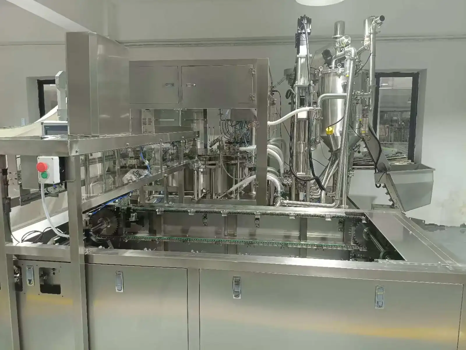
Premade spout pouch feeding track and loading arrangement
Pouch presentation is part of the accepted cycle. Confirm rod loading, track geometry, operator access and refill intervals.
Spout pouch cap feeding elevator beside filling and capping machine
Cap handling must be tested with the supplied closure, including orientation, feed recovery and low-cap conditions.

Product-to-package fit

Specify product behavior, not only the product name

“Yogurt,” “puree,” “sauce” or “detergent” does not define a filling system. The usable configuration depends on the real operating window.

Dairy-style products

Control temperature and hygiene

Provide viscosity, temperature, particles, product hold time, cleaning method and cold-chain requirements.

Juice, puree and sauce

Test flow and cut-off

Define pulp, fibers, particles, aeration, drip behavior and the fill-check method at production temperature.

Home and personal care

Review foam and compatibility

Confirm foaming, stringing, corrosion and elastomer compatibility, splash control and rinse requirements.

Center-spout pouches

Check carrier and filling access

Send a controlled drawing and filled pouch samples. Reference windows differ across the 6-, 8- and 12-head platforms.

Corner-spout pouches

Control orientation

Confirm left/right position, spout angle, pouch stiffness, filled-pack stability and change parts.

Spout and cap pair

Treat the closure as one system

Provide both components, drawings and acceptance limits for seating, torque, leakage and visible defects.

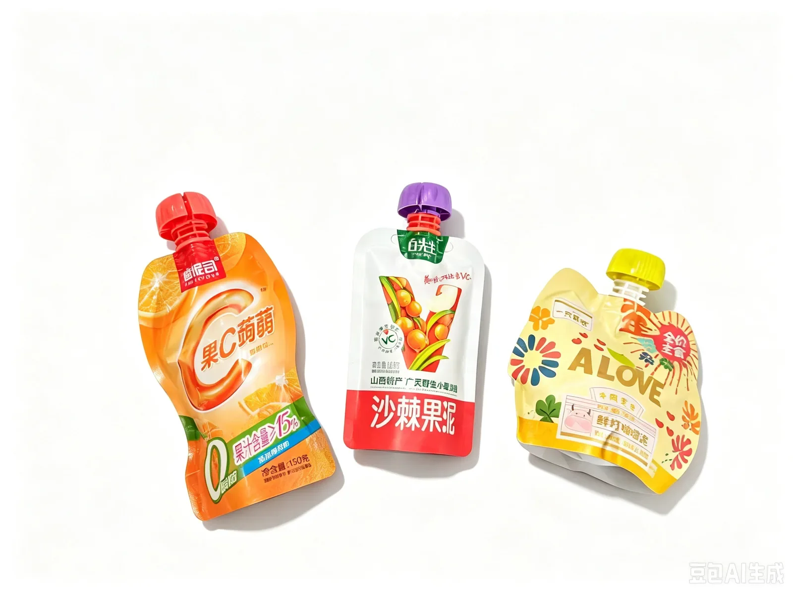
Center-spout and corner-spout premade pouch formats
Representative center- and corner-spout formats. The actual drawing and samples control the final compatibility decision.
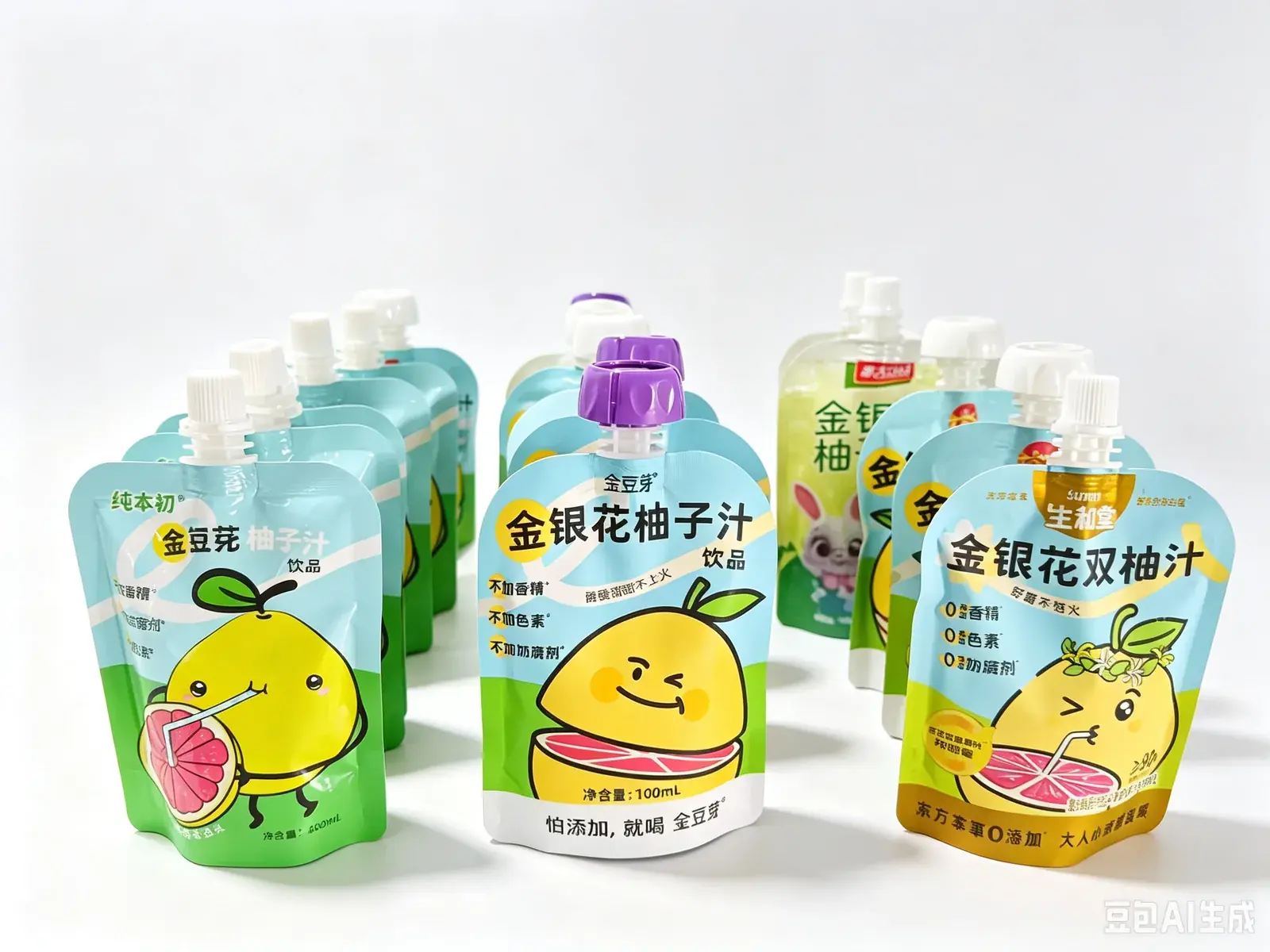
Top-spout pouch samples for liquid and paste filling trials
Representative samples for format discussion only; they do not imply one pump or head count fits every formulation.

Configuration engineering

Define filling, cleaning, capping and change parts separately

Filling architecture

Select piston or gear-pump metering from viscosity, particles, temperature, shear, cut-off, dose range and cleaning—not from fill volume alone.

Product replenishment

State how product reaches the hopper, the refill rate, level control, agitation or temperature needs and the interface to upstream preparation.

Cleaning boundary

Define which parts are cleaned in place, which are removed, circuits, media, temperature, flow, drainage, verification and ownership.

Spout rinsing

Where a rinse station is quoted, agree the purpose, media, pressure, contact point, splash control, drainage and acceptance evidence.

Cap application

Confirm cap feeding, presentation, capping motion, seating criteria, torque method, leakage test and reject handling.

Format changes

List every product, pouch, spout and cap combination; separate shared tooling, dedicated change parts, recipes and spares.

Filling and capping stations on a premade spout pouch machine
Filling and closure stations should be approved together using one controlled set of product and packaging components.
HMI and indexed turntable on spout pouch filler and capper
Agree recipe access, alarms, counts, changeover settings, language and any required line signals before FAT.

Accepted output

Compare good finished pouches, not empty-cycle speed

Accepted good pouches/hour= the slowest proven rate across pouch feed, filling, rinsing (if used), cap supply, capping and discharge × the agreed acceptance rate

Record product condition, fill volume, pouch, cap, staffing, refill method, planned stops, rejects and test duration.

Speed risks that belong in the test

  • Empty carriers from pouch-feed interruptions
  • Dose variation during product replenishment
  • Spout contamination or dripping before capping
  • Cap jams, cross-threading or incomplete seating
  • Cleaning, changeover and restart losses
  • Downstream accumulation or collection stops

The published 6-, 8- and 12-head speeds use different dose conditions. They are not directly interchangeable quotation promises.

URS and quotation inputs

Send the information that changes the machine

A complete request lets INMAYPACK compare head count and scope against the same production basis instead of returning a generic catalog offer.

When comparing offers, use the spout pouch filling machine price and quote comparison to separate the base machine, product supply, cap handling, cleaning scope and buyer-provided items before comparing totals.

01 · Product

Operating window

Composition, density, viscosity, temperature, particles, foam, stringing, target dose and allowable deviation.

02 · Pouch

Controlled format

Drawing, dimensions, material, center/corner spout position, stiffness, filled shape and physical samples.

03 · Closure

Spout and cap

Drawings, samples, orientation, seating, torque or leak limits and visible defect rules.

04 · Output

Good packs

Required good pouches/minute and shift, staffing, refill method, run time and planned stops.

05 · Hygiene

Cleaning scope

Changeover expectation, CIP boundary, rinse station, cleaning media, drainage and verification.

06 · Integration

Line interfaces

Upstream supply, coding, inspection, rejection, accumulation, secondary packing and signal handshakes.

07 · Site

Utilities and layout

Voltage, air, water, drain, room access, floor loading, service clearance and destination requirements.

08 · Evidence

FAT and documents

Materials, quantities, duration, checks, samples, video, drawings, manuals, training and open-item process.

Read the Pouch Filling Selection Guide

FAT evidence

Approve one representative production sequence

Minimum test evidence

  • Controlled product, pouch, spout and cap identity
  • Normal run at agreed dose and output target
  • Pouch-feed, low-product and low-cap challenges
  • Fill checks, closure checks, leaks and rejects
  • Changeover, cleaning and restart observations
  • Settings, counts, alarms, samples and signed results

Decisions to close before shipment

  • What exactly counts as a good finished pouch?
  • Which stops count in the output result?
  • How are fill and closure quality sampled?
  • Which products and formats are included?
  • Who owns utilities and line interfaces?
  • How are deviations and open items closed?

For a broader acceptance framework, use the stand-up pouch machine FAT checklist and define service responsibilities on the INMAYPACK service and support page.

Technical FAQ

Questions to settle before choosing head count

What does a spout pouch filling and capping machine do?

It handles premade pouches that already have a spout, meters the product through that spout, performs the agreed cleaning step where configured, feeds and applies a cap, then discharges the finished pouch.

Should I choose 6, 8 or 12 filling heads?

Choose from the required accepted output, dose range, product behavior, pouch and cap, refill rate, cleaning cycle, format changes and site constraints. The documented 6-head platform covers 30–500 mL, the 8-head reference covers 30–1500 mL, and the 12-head reference covers 30–300 mL with a higher published output at 100 mL.

What products can the series fill?

The source documents describe liquids and medium-viscosity pastes for food, beverage, personal-care and home-care discussions. Final suitability requires review of viscosity, density, temperature, particles, foam, stringing, product-contact compatibility and cleaning.

Can the machine run both center-spout and corner-spout pouches?

The 6- and 12-head documents include separate reference windows for center- and corner-spout pouches; the 8-head document gives a general width and length range. Every SKU still needs drawing review, physical samples and the correct carrier or change parts.

Is CIP and high-pressure rinsing standard?

No. The supplied 6- and 12-head reference configurations include cleaning or rinsing elements, but the final quotation must define circuits, media, flow, drainage, verification and what is included. Do not assume that every series configuration has the same cleaning scope.

How should the published speed figures be used?

Use them only as planning references under their stated fill conditions. Accepted output must be tested with the actual product, pouch, cap, operator basis, replenishment method, rejects and run duration.

What samples are needed before quotation and FAT?

Provide representative product, controlled pouch/spout/cap drawings, physical packaging samples, the SKU matrix, fill targets, cleaning requirements and proposed acceptance checks. Agree FAT quantities and duration before manufacture.

What should the quotation separate?

Separate the base machine, metering path, pouch and cap change parts, cleaning or rinsing scope, coding and inspection, utilities, line interfaces, documentation, FAT, training, service, spares, exclusions and acceptance basis.

Project inquiry

Let the real product and pouch select the configuration

Send INMAYPACK the product, dose range, premade spout pouch, cap, target good output, cleaning scope and FAT basis. We will review whether the 6-, 8- or 12-head platform is the correct starting point.

Contact INMAYPACK
  • Representative product data
  • Target fill volumes
  • Pouch and spout drawings
  • Physical pouch samples
  • Cap drawing and samples
  • Good-output target
  • Cleaning and changeovers
  • FAT acceptance rules

Tell Us About Your Packaging Project

Send your product and package details. INMAYPACK will review the application before recommending a machine configuration.

✓ Application reviewed before recommendation

✓ Project details stay private

✓ Configuration-specific technical reply